Vo všetkých redox prietokových batériách vrátane vanádiových systémov musí byť elektrolyt elektricky vodivý. Ako sa systém zväčšuje, zvyšuje sa počet článkov v elektrochemickom reaktore z jedného na niekoľko. Počas prevádzky batérie elektrolyt napĺňa kanály a rozvody, ktoré spájajú články, čo vedie ku generovaniu skratových prúdov. Tieto skratové prúdy ovplyvňujú Coulombickú účinnosť zväzkov redoxných batérií, čo vedie k zníženiu celkovej energetickej účinnosti a spiatočnej účinnosti systému.
Hodnota bočného prúdu medzi článkami závisí od niekoľkých nasledovných faktorov:
- Počet článkov v batériovom zväzku.
- Geometria rozdeľovačov a prietokových kanálov.
- Vodivosť elektrolytu (vrátane jeho chemického zloženia).
- Stav nabitia (SOC) elektrolytu počas cyklovania batérie.
- Prevádzkový prúd.
Ak je počet batériových zväzkov a chemické zloženie elektrolytu pevne dané, najúčinnejším spôsobom zníženia skratového prúdu je zúženie rozdeľovačov a použitie tenších a dlhších prietokových kanálov. Nadmerné predlžovanie prietokových ciest môže mať za následok vysoký pokles tlaku v batériovom zväzku. Vysoký pokles tlaku je nežiadúci, pretože zvyšuje spotrebu elektrickej energie čerpadiel. Výpočty skratového prúdu by sa mali vykonávať spolu so simuláciami dynamiky tekutín, aby sa vyrovnali hodnoty skratového prúdu a poklesu tlaku.
V Inohub Energy uprednostňujeme monitorovanie hodnôt skratového prúdu pre naše batériové zväzky a aktívne sa podieľame na simuláciách skratového prúdu a dynamiky tekutín.
POĎAKOVANIE:
Táto práca bola podporená projektom: IPCEI_IE_FLOW_BESS_012021_2. fáza
Ilustrácie:
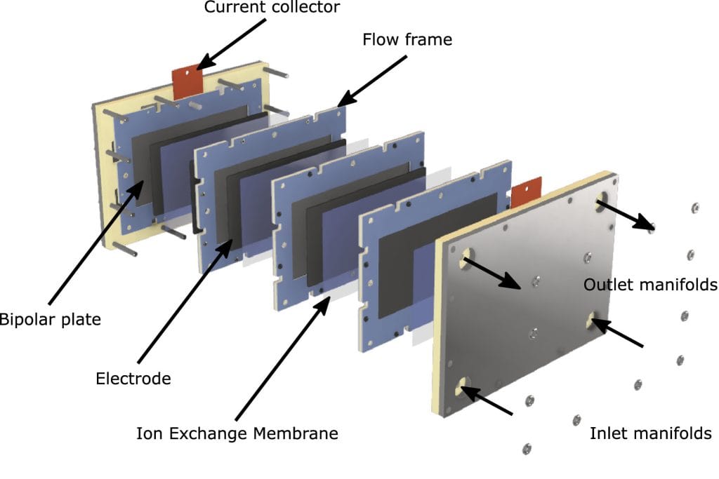
1) Príklad časti 4-článkovej zostavy redox prietokovej batérie.ack.
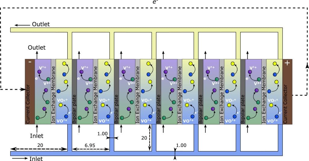
2) Schematické znázornenie vanádiového redox prietokového batériového zväzku VRFB pri nabíjaní so 6 článkami a rozmermi kanálov prietokového rámu a rozdeľovača (in mm).
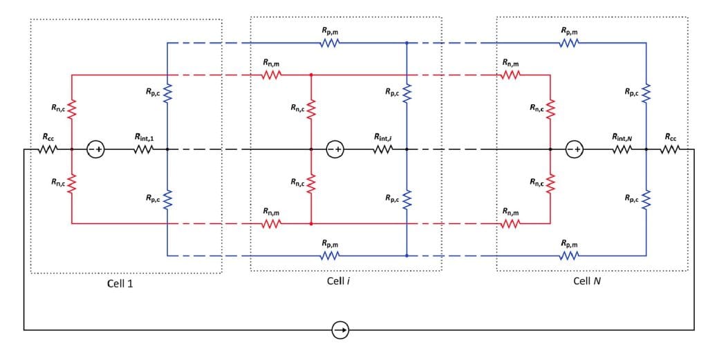
3) Schematické znázornenie modelu ekvivalentného obvodu použitého na simuláciu skratových prúdov v zväzku VRFB s N článkami
Zdroj ilustrácií: Nuno M. Delgado, Ricardo Monteiro, Jorge Cruz, Anders Bentien, Adélio Mendes, Shunt currents in vanadium redox flow batteries – a parametric and optimization study, Electrochimica Acta, Volume 403, 2022, 139667, ISSN 0013-4686, https://doi.org/10.1016/j.electacta.2021.139667.